
|
|
|
|
|
|
|
|
|
|
|
|
|
|
|
|
|
|
|
|
|
|
|
|
|
|
|
|
|
|
|
|
|
|
|
|
|
|
|
|
|
|
|
|
|
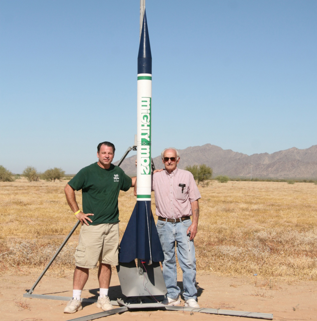
My Dad: |
Estes Industries |
Apogee
Components (RockSim) |
National Assoc. of
Rocketry |
|
|
Public Missiles
Ltd. |
PerfectFlite
Electronics |
Missile Works |
Newton's
Third Rocketry |
Spherachutes |
|
|
AeroTech
Consumer |
What's
Up Hobbies |
Giant Leap
Rocketry |
|
|
Essence's |
JimZ Rocket
Plans |
CW Graphics |
Sticky Stuff
Sales |
Microfasteners |
|
The Home Depot |
Granger Industrial
Supply |
Radio Shack |
Lowe's Home Improvement
Center |
Just Rockets: |
I want to say thanks to Scott of the now closed
"Just Rockets" of
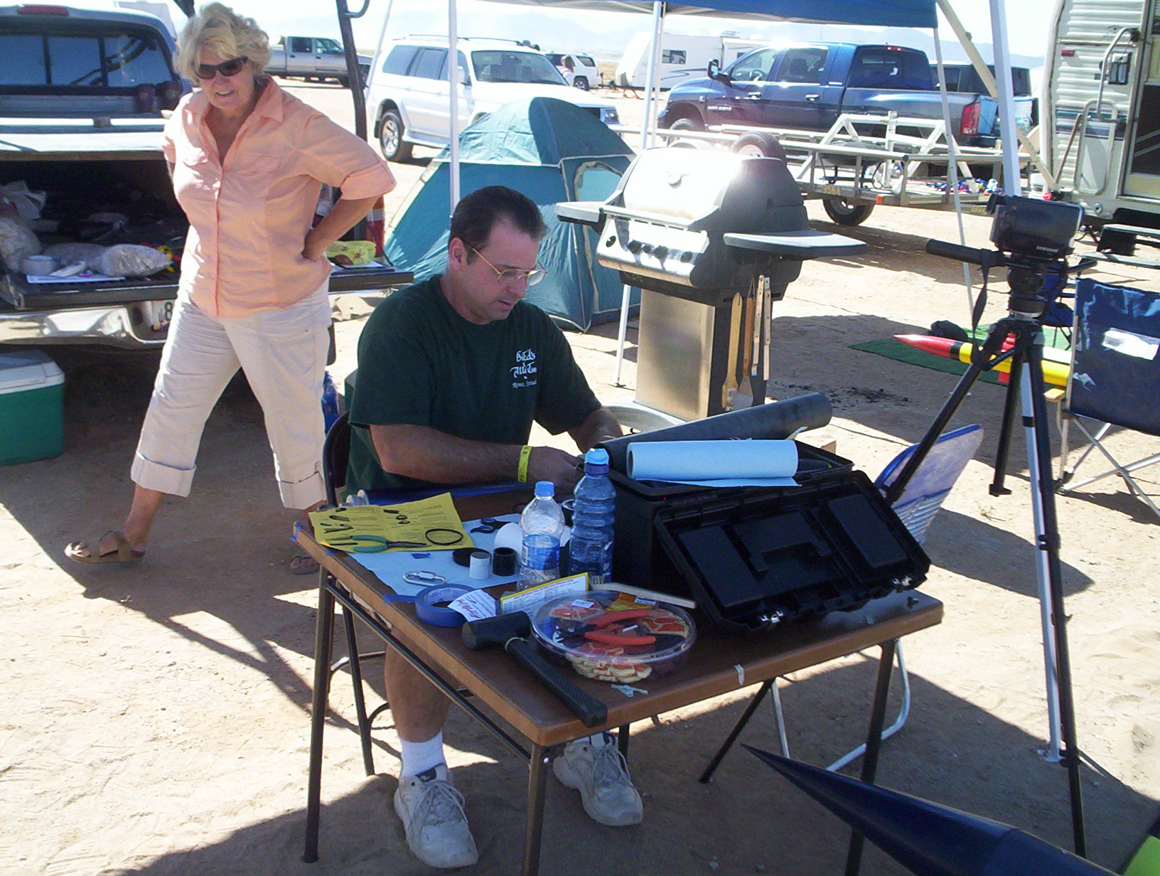
And lest we forget the members of the Superstition
Spacemodeling Society for their invaluable advice and assistance during the
project, particularly Gerald, Geoffrey, Dwain, Mark, Scott, Darrel, Bob and
Terry. If I've forgotten anybody, I'm sorry!
And finally, I'd like to thank my Father and dear departed Mother for their
unwavering support through the years. Their unconditional love has undoubtedly
guided me along a path leading to personal success. Of course, I'd be remiss if
I forgot to give a big hug and kiss to my little "Bear" for putting
up with Daddy's little eccentricities. Thanks Mom, Pop, and Bear!!