Aeromoe and The Rocket Doc
Upscale Estes CHEROKEE-D Project
The CHEROKEE-N


Project Start Date: 7 November 2009
Actual Flight Date: 24 April 2010


Brad and I assisted at the Orbital Science Corporations annual "Rocket Derby" in Chandler Arizona on November 7th. During the course of the day, we started kicking around the idea of doing an upscale Estes CHEROKEE-D. I've recently built a couple smaller high-power CHEROKEE-D rockets and Brad was kind enough to lend his finishing skills to them. After two successful flights, the 38mm-powered version suffered a broken shock cord during our October G.H.S. launch at Rainbow Valley and Brad was a bit "traumatized" by it. That rocket should be repairable, but in the meantime, we agreed to push forward with a much larger version. This webpage exists so we can document the conception and build progress of this rocket.

Below are some screen shots from Estes catalogs (1970, 1971, 1975) as well as some of my CHEROKEE-D models.


First, some photos of some of my smaller Cherokee rockets:


Estes Clone D12-7

2.2" H128W

2.2" I300T

3.1" K695R

3.1" K695R

3.1" K185W

3.1" K270W

2.2" J500G

The final photo is the repaired 2.2" version on a J500G "Mojave Green" on 13 February 2010.
The K695 hit 8260 ft, the K185 hit 8351 ft and the K270 flight hit 11,048 feet...all three were successive personal bests for me.


And here are some launch photos of the rocket described on this page...the Cherokee-N!


Click Here to view High-Def on-board video on You Tube.

Click Here for my tutorial page on making large nose cones.


By the way, the background photo on this page depcits the first launching of the Cherokee-N on an Aerotech N2000W on 24 April 2010 at Rainbow Valley. The flight was a nearly a complete success as she soared to over 7400 feet and successfully dual-deployed. Please click here for a brief synopsis of the flight and more flight photos.


Such a large project requires much planning if it's going to be successful. In 2008 I learned a lot during the upscale Mighty Moe project for my NAR Level 3 certification. One goal for this project is to reduce costs as much as possible by using locally-available materials and doing a lot of our own component cutting. True, ready made centering rings and custom-cut airframe tubes are convenient, but the costs begin to add up quickly. During 2009 I've become pretty adept at cutting my own centering rings so I'll apply that skill to the CHEROKEE-D. Many rocketeers do much of the work themselves and I'm beginning to see the cost benefit of that. Also, the nose cone for any large project can be a major concern, and unless you're willing to settle on one of the generic "ogive" cones out there you have to create one yourself. Besides, we're using "non-standard" aiframe components so a custom made cone is a necessity.

Besides cutting costs, some of the goals for the upscale CHEROKEE-D are:

- True upscale of the Estes CHEROKEE-D. Both Brad and I are very fond of the clean design of this Estes classic.
- 98mm (four inch) motor tube so we can fly on the more powerful "M" motors and possibly an "N" motor. We already decided the first flight will be an N2000W. :)
- Provision for onboard video.
- Redundant electronics for more reliable recovery.
- Additional electronics for GPS tracking.
- Custom made vinyl decals.

Upscaling the CHEROKEE-D to an M-capable project is not a new concept. At least one other fellow has tackled the project and he has a webpage dedicated to the project. Of note is that his design deviates from being a "true" upscale in that his rocket is (admittedly) longer than it should be. Also, he (erroneously) used a conical nosecone whereas the CHEROKEE-D nose cone is secant ogive...that's how the Semroc webpage describes their clone of the Estes BNC-55AC. Otherwise it's an impressive project and I'm sure to glean some useful information from his labors.

Speaking of nose cones, here is an esoteric webpage I found describing the geometry of various nose cone shapes...very informative. And MASA-Planet has a very informative series on turning nose cones on a lathe, beginning with this weblink. Here is Part 2, and here is Part 3 of the series. If lathe work is your cuppa, I recommend you check it out!

7 NOV 09

After Brad and I discussed the project, I got home and ran the upscale numbers. We'd discussed an 8-inch diameter airframe so that's what I went searching for. I went to the local home improvement center and checked out their concrete forms. These relatively inexpensive tubes come in 48-inch lengths in various diameters. They had plenty of 8-inch (nominal) tube in stock so I grabbed a tape measure and measured the diameter. The largest 8-inch tube was actually 8.5 inches and I managed to find six of them. Three pieces would cover the length but I wanted to double the thickness of the airframe so I picked up all six of them. I also picked up a two-foot square piece of 1/2-inch baltic birch plywood for some centering rings.

After getting home, I ran the calculations for the 8.5-inch diameter tube. Based on the original kit diameter of 1.325, I divided that into 8.5 and came up with 6.41 for my scaling factor. All dimensions would be multiplied by that for the upscale. Instead of the original K-47 16.35-inch body tube, I elected to do the later 18-inch length- scroll down the page for #1247. Estes increased the length to enhance stability. For the upscale, this yielded an airframe length of 115 inches, give or take. The three 48-inch long tubes would more than cover this and I'd have enough left over to do the electronics bay and possibly the fin can coupler. I also upscaled the nose cone dimension. The original BNC-55AC was 5.375" long so that became 34.45" for the big bird...barely doable on my 36" capacity lathe. I'll have to turn the cone and some of the shoulder, then turn another shoulder to attach...no problem. Since the fins are not swept back on the CHEROKEE-D, overall length is just over 149 inches, or 12 feet, 5 inches. This was quickly becoming the largest rocket project I've worked on.

I started building the rocket in RockSim to see how I could make best use of the tube lengths. In short, the upper payload bay is 46 inches, the lower payload bay 37.5 inches, and the fin can is 34 inches. The e-bay connects the upper and lower payload bays and has a two-inch length of airframe separating the two tubes. This piece is where we'll locate the switches for the electronics as well as the static ports for the altimeters.

Below is a screen shot of the CHEROKEE-D in RockSim up to this point.


After finalizing the dimensions, I started cutting the tubes. I marked the tubes and cut some strips of poster board to wrap around the tubes as cutting guides. A couple wraps of thick paper makes a decent guide to draw the blade against and cut the tubes off squarely. A sharp #11 blade in the hobby knife made the job fairly easy but also requires many passes to cut all the way through the tube. I even managed to avoid slipping and cutting myself during the process. Within an hour or so I had all six airframe pieces cut. Because these tubes are meant for concrete, the inside has a layer of wax paper that needs to come off. It's just like removing the glassine from the outer surface of many commercial body/airframe tubes...it comes off as a spiral if you're lucky and take your time. Below is a photo of the three tubes:


Next came the job of slicing and fitting the internal "doubler" tubes. Again with a sharp blade, I sliced each tube down the length. I then compressed the tube and put it inside the outer airframe so I could mark the overlap. Remove the tube, connect the overlap marks with a line and cut along that line. This creates a tube that nicely fits inside the main airframe and effectively doubles the thickness. Eventually, the tubes will be epoxied together with a layer of epoxy between them and the tube ends sealed with epoxy. With a decent amount of progress made less than 12 hours since project inception I decided to call it a night.


8 NOV 09

Today I started working on the e-bay tubes, duplicating the slicing operation as I did on the main airframe tubes so we would have a double-walled e-bay. However, in this case I had to slice both tubes since I would be decreasing the diameter even further to fit inside the doubled main airframe. Before doing this I'd made a trip back to the home improvement store to see if they happened to have a tube that would just fit inside the doubled main airframe...they didn't. The tubes they had on hand were about 1/8-inch too small...much too sloppy a fit.

I mixed up some epoxy and nested the tubes together. I put a piece of wax paper along the outside joint and shoved the assembly inside one of the airframe tubes so it would cure up at the proper diameter. I checked on it a little later and the epoxy hadn't set up very well, so I had to start over with the epoxy. This time I got a good slathering on both joints and shoved it home again. I checked on it a little while later to make sure it wasn't glueing itself to the inside of the airframe...it wasn't. I left it alone for a few hours and when I checked on it again, I had a nicely formed e-bay. The only problem was this time the edges (circumference) weren't perfectly aligned so I had to figure a way to square them up. In the end, I just shoved the e-bay down inside an airframe tube until just enough was protruding that I could cut it away with a sharp knife. Because of the cured epoxy between the tubes, this was a little more tedious but in less than an hour I had both ends squared up, losing only about 3/4" tube length in the process. Even allowing for the two-inch piece of airframe at the center, we still had nearly 8-inches of "coupler" on each end to fit inside the corresponding payload bays.

Another task I started today was cutting motor mount centering rings. I like to use my Dremel tool with the circle cutter attachment to cut rings. Because of the thickness of the plywood, I cut each ring in two phases. First I measured the diameter as closely as I could, then drilled the 1/8-inch starter holes: one in the center and one at the outside edge of the desired diameter. Then I set the bit depth to about half the thickness of the wood, and made the first cut. Then I flipped the wood over and repeated, completing a ring. I used a rasp to clean up the edge a bit and test fit in a doubled airframe tube. The ring fit very nicely. I did six rings total today and they all came out very nice. Since I don't have a motor tube yet, I haven't cut the center holes out. I'll do the bulkplates for the e-bay in the same manner. Below are some photos of the ring cutting process:


9 NOV 09

This evening I procured the motor tube. My buddy Rick from the club brought me a 4-inch diameter mailing tube from Fedex Kinkos. Thick-walled and 48 inches long this tube is almost perfect for a 98mm motor. The only problem was the aft closure on the motor case slipped right past the edge of the tube...it's just a wee bit too big. I pondered how to make it work and I came up with a fairly cheap solution. I had a piece of LOC 4-inch tube and after I peeled the white layer off, the tube was a very tight fit inside the mailing tube...and the aft closure didn't go past it. This would work good as a liner to create the correct diameter but I'd need something else to positively stop the motor from travelling forward under thrust. There are all kinds of fairly expensive options out there: Aeropac retainers, proper motor tubes, etc etc. But I want to solve the problem in the most cost effective manner...final outcome pending.

The motor tube took a bit of preparation. The white outer layer was pretty thick and it took considerable effort to get it peeled off down to the first brown layer. I'll decide on a final length for the tube once I get more work done on the fin can.


11 NOV 09

Today I was able to cut out the three fins from 1/2-inch birch plywood. I used a 1/4-inch radius bit in the router to put a nice round edge on the outer edges of the fins. These are pretty big fins - the root edge is over 23 inches long and the span of each fin is just over 15 inches.

I also marked up the motor tube for the centering ring positions. For this rocket, we'll have three centering rings divided evenly over the length of the fin root. The center ring will be doubled up for some additional strength. The upper centering ring will be notched on the rear side so the tops of the fin tabs will seat into the notches. I may do the same for the lower ring. Three rings will make it fairly easy to add fiberglass to the joints where the fins pass through the airframe. The fin can airframe will have fin slots cut all the way to the bottom of the airframe. That way, I can temporarily assemble the fin can while the fins are being epoxied to the motor tube. Once they are in place, I can remove the fin can airframe and fiberglass the fin root / motor tube joints. At this point, only the central centering rings will be epoxied to the motor tube. The upper and lower rings will wait until I get the internal glassing done. This is how I envision doing the internal glassing:

Insert the fin/motor tube assembly in the fin can, and epoxy the middle centering rings to the inside of the fin can, temporarily placing the other centering rings so the motor tube is correctly aligned. Once that joint is cured, I'll remove the upper centering ring and fiberglass the upper fin/airframe joints on the inside. Then I'll repeat the process for the lower joints. Once all the joints are finished I'll epoxy the rings in place.

I also started cutting out the center holes in the motor mount centering rings.


18 NOV 09

Made a little bit of progress the past couple of days. I cut the rings for the coupler at the top of the fin can. These are doubled up for strength since the recovery harness u-bolts attach to these. I picked up two 2-inch, 5/16-inch diameter u-bolts today and mounting hardware. I drilled the holes for them and after applying wood glue to the mating surfaces of the rings, I clamped the rings together and attached the hardware. These rings will be recessed inside the top of the coupler about a half inch so I can apply a decent epoxy fillet to the joint. Below are two photos of the completed assembly.


I also made the fin can coupler out of more of the 8.5-inch sonotube. Again, I sliced it to reduce the diameter. Like the main airframes, I doubled the thickness by epoxying another section of sonotube inside the first one. So it would cure up at the proper diameter, I placed the pieces inside the fin can tube while the epoxy cured. To prevent it from gluing itself inside the fin can, I lined the inside of the fin can with wax paper where the outside joint was...just like I did while making the e-bay. This rocket is going to be built like a tank. It has to be to withstand the forces of flight under "N" impulse, and safely recover it's own weight.


19 NOV 09

Today I cut the fin slots in the fin can tube. I did the first one with a Dremel tool and cut off wheels but I kept breaking the wheels so for the other two I just used a jig saw. The saw went much quicker and worked just as well as the cut off wheels.

I also emailed a machinist acquaintence of mine and asked if he could fabricate the aluminum motor-stop ring for the rear of the rocket...haven't heard back from him yet.

Another task I completed was gluing together the two central motor mount centering rings.


21 NOV 09

Today I started in on the project early in the morning. Below is a photo of the central ring and the first test-fit of a fin in the fin can. I also double-checked some measurements and decided to take the big step and epoxy the central ring to the motor tube. As such, construction on the Upscale CHEROKEE-D has officially begun.


Also, tonight I attached the first fin. I used the fin alignment jig I made for the Mighty Moe to align the first fin. Also, below is a photo of the recovery harness attachment points at the top of the fin can. The motor tube hasn't been cut to the final length yet, and the centering ring is in place only temporarily to keep the motor tube aligned while the first fin sets up.


22 NOV 09

Last night I finished "doubling" the remaining two airframe tubes by epoxying the inner tube inside the outer tube. This afternoon I attached the second fin to the motor tube. Below is a photo of the second fin while the epoxy is curing up.


23 NOV 09

This morning I attached the third fin to the motor tube. Once the epoxy is cured I can begin to strengthen the fin roots with Kevlar and epoxy.

I also went over to Joel's place and picked up the aluminum motor-stop ring he machined for me. This piece is very nice and he even drilled it for me. Three holes are countersunk for 1/4-inch screws will be used to secure it to the rear centering ring. Three more holes can be used for motor retention. The only issue with the ring is it is a very tight fit on the motor casing. I'll file the inside circumference a little bit to increase the clearance a few thousandths.

Below is a photo of the three fins epoxied onto the motor tube. Next to that is a photo of the aluminum thrust ring Joel fabricated for us.


24 NOV 09

Today I started to make some more progress on the e-bay. I'd already put a third piece of airframe inside the doubled-up e-bay to act as a sort of "stiffy coupler" like LOC uses in their e-bays. This piece will also serve as the internal "stop" for the bulkplates.

I also found the fit of the e-bay too tight inside the adjoining airframe tubes. So I peeled off the outer yellow layer of paper from the e-bay to reduce the diameter. It helped, but not quite enough. I'm going to have to work on the inside of the aiframes some more to increase the inside diameter. I also plan on soaking the outside of the e-bay with CA then sanding it smooth to reduce friction. Probably have to do the same on the insides of the airframes.

While the e-bay was nested inside the lower payload bay, I drilled the six holes for the 1/4-20 screws and tee-nuts that will hold them together. The upper payload bay was still too tight a fit so it'll have to wait.


26 NOV 09 - Happy Thanksgiving!
As usual, I was up early today and started working on the CHEROKEE-D. I made some progress by drilling the rear centering rings to accept the mounting hardware for the aluminum stop plate as well as the motor retention hardware. The stop plate is secured by three countersunk 1/4-20 machine screws while the motor retention is three 3/8-inch bolts.

I also decided to notch the inside of the innermost ring so the lower edge of the fin tabs will have a place to sit. To accomodate this I had to cut about 1/4-inch off the end of the motor tube. Otherwise the centering ring assembly was about 1/8-inch away from the rear of the fin tabs. I also plan on securing the centering rings to the fin tabs with screws.

Below are some photos of this progress. The final two photos show a "baby" 98mm motor case and rear closure fully seated and then sticking out of the rear of the motor tube.


I also drilled the holes in the upper payload bay and e-bay for the 1/4-20 tee nuts.

Later in the day I built a couple of stands so I could transport the fin can on the back of my truck. I was heading out to Brad's for Thanksgiving dinner and I wanted to take all of the components and show him our progress. After I arrived we assembled the rocket for the customary photo. Only thing missing at this point is a nose cone.


29 NOV 09

The photo below shows the first batch of Kevlar reinforcing I've applied to one set of joints. I have the Kevlar cut for the others and it's just a matter of time till I get them applied.

Cutting the Kevlar without proper shears can be frustrating, but I found out a way to do it fairly painlessly. Run a bead of thin CA along the line you want to cut and after it dries, a very sharp razor blade will cut through the material after a couple of swipes. I use wax paper under the Kevlar while the CA dries and then peel off any if it happens to stick.

Applying the Kevlar takes some patience as well. It is not readily absorbant, so be sure to use really slow setting epoxy so it'll have hours to seep in, both top and bottom. I spent some time (30 minutes or more) just working the Kevlar and epoxy with a wooden tongue depressor until I was pretty certain I could leave it to set up.


30 NOV 09

Last night I completed the second set of Kevlar reinforcements on the fins/motor tube and this afternoon I did the third set. This milestone will enable me to start assembling the fin can in the next day or two. After that I can start the internal reinforcing of the fins to where they meet the inside of the airframe tube.


2 DEC 09

This photo shows my method to keep the fin can airframe tube in place against the centering rings while the epoxy was curing to the central centering ring. It worked out pretty good.


5 DEC 09

With the fin can airframe in place and the fore/aft centering rings out of the way for now, I started doing the internal glassing the past couple of days. I finished the third set of two on the morning of 5 December. Late in the evening of 5 December all the internal glassing was cured up so I decided to install the aft centering ring doublet. Below is a photo looking down into the fin can from the rear.


First off, I had to prep the inner centering ring by epoxying the six tee-nuts in place. Once the epoxy was well set up, I was able to secure it in place. I slathered a decent amount of slow-cure epoxy on the inside of the airframe, on the rear of the fin tabs, and the motor tube. I carefully aligned ring and pushed it into place. I then secured the ring to the fin tabs with six coarse-thread drywall screws. After I slathered more epoxy on the top of that ring and around the perimeter of the airframe and motor tube I placed the outside rear centering ring in place. I then inserted the three 3/8" motor retention bolts into their holes and tightened them down to sort of "clamp" the rings together.


Then I started cutting 1-inch wide rings of Sonotube to apply to the inside rear of the airframe. These concentric rings serve to further strengthen the rear of the airframe by making it considerably thicker than just the main airframe. A generous layer of epoxy between each successive layer should strengthen the tail end of the rocket. Below is a photo of a representative ring and three of them curing up inside the rear of the rocket.


6 DEC 09

Today I've been pretty busy on the CHEROKEE. The rear of the fin can has a slathering of epoxy on the concentric rings setting up. During all this epoxying I've also managed to get the rest of the tee-nuts inside the e-bay secured in place. The third photo shows a photo a few days later with the aluminum motor thrust plate installed. It also illustrates the thickness of the rear of the airframe after all the concentric rings have been installed and the epoxy on them cured up.


Another aspect of the project that is beginning to take shape is the provision for onboard video. Earlier in the week I'd decided we'd mount a small HD video camera between two of the fins. After a few days thinking about this, I decided it would be possible to move it up the airframe to the lower payload bay. One of the reasons for this decision was to minimize the risk to the lens of the camera during initial ignition and boost. I've witness a lot of debris getting kicked up during White Lightning ignitions and I felt the fin can location was too close to the business end of the rocket, so I sought another solution.

Knowing the dimensions of the HD video camera, I constructed a small box of light plywood that would be sealed on the inside of the lower payload bay but with an access hatch on the outside. The configuration of the Samsung R10 camera is such that the lens is oriented 25 degrees off-axis. It is possible to mount the camera with the lens outside of the rocket facing down along the airframe. This way, no mirrors are necessary. In this mounting configuration, the typical 1/4-20 tripod mounting hole on the bottom of the camera faces "up", so it is possible to mount an angled metal bracket on the outside of the rocket above the camera port and mount the camera to the bracket. It will be necessary to fabricate a streamlined fairing that attaches to the side of the airframe above the camera to reduce drag. Please check out Vern Knowle's impressive website for lots of great projects in High Power Rocketry. Follow this link for one solution he came up with to create a streamlined mirror hood for an onboard video camera.

Below are some photos of the camera box construction:


This evening I also made a mounting bracket for the HD camera. I used a piece of 1/8-inch thick steel that is one inch wide. I bent this piece in a bench vise to match the angle of the camera. I also drilled three holes in it to accept 1/4-20 mounting screws. Two of the screws will secure the bracket to the airframe and the third will secure the camera to the bracket by using the camera's tripod mounting hole.

To mount the bracket to the airframe, I drilled two matching holes just above the access hatch. For the hole that is inside the camera box, I used FixIt epoxy clay to secure a 1/4-20 barrel nut. For the hole that is just above the box, I used a tee-nut. I had to grind the tee-nut down about 1/8-inch so it would not protrude through the side of the airframe. The epoxy and fiberglass that secures the box to the inside of the airframe was still not cured, so when I attached the tee-nut, it tightened down into the epoxy and fiberglass. For a little added insurance, I dabbed on a little more epoxy to the tee-nut.

Below are a couple more photos a few days later with the camera mounted in place. I still have to make a cover plate for the outside of the opening and the fairing.


9 DEC 09

Made a little bit of progress tonight. I did the fiberglassing on the second set of internal fin / airframe joints. After a couple of hours I noticed epoxy running down one of the fins: I'd forgotten to tape the external joint and epoxy was seeping out through the seam. DOH! Since this is very slow curing stuff, I was able to easily remove it and wipe the fin down with alcohol to clean it up. I then applied the tape.


10 DEC 09

Tonight I decided to fiberglass the third set of internal joints. With the internal glassing done, I'll be able to add the upper centering rings soon. Below is a photo looking down into the top of the fin can showing some of the fiberglassing on the joints.


31 DEC 09

OK, so it's New Year's Eve here in the USA and I'm home working on rockets. No worries, I'm not much of a party animal so I'll just press on with what makes me happy. And yes, it's been three weeks since I've made any updates to this webpage. Progress on the CHEROKEE-D has been slow since earlier in the month but that's only because I'be been working on other projects as well.

My second attempt at making a hood for the HD camera came out pretty good I think. After discarding the first attempt using wood as a base, I decided to sacrifice an Estes Big Daddy nose cone. I sliced it in half lengthwise and layed a couple layers of fiberglass over it. I think it came out pretty decent. Some 6-32 screws and tee-nuts will secure it to the side of the airframe.


Happy New Year, by the way! To Be Continued...


31 JAN 10

Wow, it's been a month since I've made any progress and updated this website. Been a buzy month with some other activities going on but so it's definitely time to roll up the sleeves and get some work done on the CHEROKEE-N.

During December and January I decided to build the rocket rotisserie. I bought a BBQ rotisserie motor at Wal-Mart for a little over $20. The fittings are Schedule 40 PVC. The central support tube is 2" PVC. I used various hardware to construct the 2x4 support posts and attached them to circular ends from a wire spool. At this point it's not the most stable set up but it's functional. Rick put some 25 pound dumbells on the pads for additional stability.

Yesterday was a good day for working on rockets. I was working on the rotisserie posts all morning and right up to the time I packed up the truck to head over to Rick's place. I met Brad at Rick's and we proceeded to do the Giant Leap "socks" on the two main airframe tubes. The socks are not fiberglass but rather a polyester-type sock you roll down the airframe and apply epoxy resin to. These are seamless so finishing work is reduced a bit in that respect. However, the Sticky Stuff epoxy I used did not completely fill in the weave so we'll probably apply a finishing coat of resin to smooth it out.

Below are some photos of Brad and Rick doing some of the fun work.


6 FEB 10

Today Brad, Rick and I did a little more work. We glassed one section of the fin can with six-ounce glass and West System 206 slow cure hardener. We also used the West System to apply a finishing layer of resin to the larger piece of airframe tube. In the third photo Brad inspects the finish while SSS club member Geoffrey Kerbel observes.


9 FEB 10

Tonight I finally started laying up the nose cone. I'd already cut several "stop sign" shaped pieces of 1x10 pine for the nose cone. I decided I'd use these initial pieces as the shoulder for the nose cone. I use a piece of 5/16" all-thread and clamps to keep the pieces in place while the wood glue cures. When cured, the all-thread will come out and I'll drill and tap the central hole for 1/2" all-thread that I'll use to secure the piece to the lathe and turn the shoulder to the proper diameter and length.


13 FEB 10

After a "hard" day of flying and recovering rockets at Rainbow Valley, Geoffrey, Rick, and I met up at Rick's for an impromptu build session. Basically we accomplished the all-important task of finishing the tip-to-tip glassing of the fin can. Below are some photos Geoffrey took with my cell phone camera. Thanks for helping record the moment, Geoffrey!

Also I have some photos of the beautifully-rebuilt (by Brad, The Rocket Doc of course) 2.2-inch "CHEROKEE 38" before, during, and after the flight today. It was a single-deploy flight and that Aerotech J500G (with an RDK-14 Delay Kit - thanks Terry!!!) really put the rocket up there. Thanks to some eagle-eyed trackers I was able to finally locate it just a few seconds before it touched down to the southwest of the launch area. I jumped on one of Mark W's ATVs and made a quick recovery of the rocket. The third photo shows some flight damage to the black fin that Rocket Doc will probably repair for me. The trailing edge got dinged up pretty good and the fin is also cracked along the chord. Incidentally, Brad did a great job of re-finishing my custom-turned nose cone after it sat in the desert for a couple months. And, finally it may not be immediately evident in the photos of the 2.245" (BT70H) rocket, but I goofed up on the scaling of the fins. Only after I finished scratch-building the rocket did I realize I'd accidentally sized the fins for the larger, 2.64" diameter BT-80H. Therefore, they are a bit larger than they should be for this airframe diameter. No worries as I plan on building a BT80H and most likely I'll make another BT-70H sized-airframe for my pretty nosecone. Thanks to Scott Hertel for loaning me the motor case for the flight.


19 Feb 10

During the past week I’ve made some reasonable progress on the CHEROKEE-N. For one, I made a significant change in the construction of the nose cone. I decided NOT to turn the cone on the lathe after all. Rather, I’m in the process of building the cone out of plywood formers and blue-foam around a central heavy-duty 3-inch tube. The top one-quarter of the cone will be turned on the lathe and will fit into the 3-inch tube. So, the two photos above of the wooden shoulder being laid-up are a moot point. Below is an early photo of a test-fit of the current configuration.


To this end, I finally decided to build my vertical rotisserie for the hot-foam cutting bow I made last year. Rick and I spent Sunday evening constructing the rotisserie and when I got home I went to work cutting pieces of blue foam. At that point I’d still not decided on the “final” plan to use ¼-inch plywood formers for the shape of the cone…that decision came later in the week. The foam I cut should still be usable as all I have to do is cut each piece into quarters and attach them to the central core and profile plates in a stacking fashion.

Below are a couple of photos of Rick with the rotisserie.


The double-walled shoulder of cone was made from the same tubing as the airframe and is a separate assembly from the nose cone proper. I had to do the standard “slice-and splice” to get the outside diameter sized correctly. I then sliced off one-inch sections to use as internal “shoulders” within the nose-cone shoulder to give the bulk-plates a positive stop. I used my handy Dremel tool with circle cutter attachment to cut the bulk-plates. The bottom of the shoulder has two bulk-plates: one inside the shoulder and one on the outside, the same diameter as the shoulder. Since the nose cone proper has a plywood bulk-plate on the bottom, there is just the internal bulk-plate at the top of the shoulder. Below are some photos of the cone shoulder components.


The central core tube is a heavy-duty shipping tube with walls nearly ¼-inch thick. At the top of the tube is a ½-inch thick centering ring that matches the diameter of the cone profile at that station of the nose cone. I cut four (later increased to eight) “profile plates” from ¼-inch craft plywood that fit between that centering ring and the bottom “bulk-plate” at the base of the nose cone. Two additional centering rings spaced along the tube provide additional alignment for the profile plates. The lower ring of the two is wide enough that I added four ¼-20 tee-nuts on the top side of the ring to provide anchor points for the ¼-20 threaded rod that will help secure the nose cone to the shoulder assembly. Other than that, the two rings don’t contribute much to the structural integrity of the cone. Below are a couple photos from a short build-session at Rick's on the afternoon of the 19th. First photos show the core tube with the first profile board attached. The next photos shows the drogue recovery bay airframe on the rotisserie after applying a filler coat of West System.


If all goes well with the foam cutting and the cone looks good, it will get covered with glass and resin.


22 FEB 10

Today I made some good progress on the nose cone. After returning from an expedition with Brad to Hie-Tek Automation for a piece of 1515 rail, I came home and got some sleep…but not much. Brad and I had been discussing options for foaming the nose cone, and sometime during the evening we were chatting on the phone about liquid expanding foam. Since I had some two part foam on hand, I decided to give it a try on the nose cone. I built up cardboard “dams” to contain the foam on both ends of one of the eight troughs created by the profile pieces. I then made cardboard dams on the outsides of two adjacent profile pieces to further contain the foam. All the dams are lined with wax paper to keep the foam from curing to the cardboard The idea here is to build up the foam in poured layers so it cures up considerably higher than the profile pieces. Once cured, the foam can be rough cut with a hack saw then sanded to the final desired shape.

I made several pours of the foam and I was pleased to see it rise up above the profile pieces while remaining contained within the dams. After four pours the first trough is still not completely filled, so it’ll take a lot of liquid foam to complete the cone. I got Brad back on the phone to discuss my progress but we were still wallowing about how to eventually sand the foam to the final shape. Still later in the evening while pondering the idea I had an epiphany about how to sand the foam: go back to square one, put the cone on the lathe and sand the rough-cut foam to shape. I called Brad to discuss this and he agreed it was probably the best solution for the situation.

Satisfied I’d found the solution to that problem, I was eager to move on with the remaining component of the nose cone: the wooden tip. It had been chucked in the lathe since Friday, waiting for me to hit the power switch and start working it. I decided to take the plunge while I had Brad on the phone. I described one recurring problem I’d been having with my turnings: the fact the tailstock often wanders to the right as the lathe is spinning…often before I’ve even made the first cut with a tool. As we were talking, it happened again, so I turned the lathe off and loosened up the tailstock. I completely removed the cone stock and sanded the bit of dowel that was sticking out from the right side of my cone stock. I then found the center and drilled a hole in it so I could place a 10-24 tee-nut on the end for the tailstock point to contact. I’ve done this a couple times in the past and it tends to reduces the amount of “wandering” the softer pine wood is susceptible to.

So I re-install the cone stock in the lathe and move the tailstock into place. The good thing about using the 10-24 tee-nut is I only have to move the tailstock into position and tighten it to the lathe bed. I powered up the lathe at one of the lowest speeds and started making wood chips. I was pleased to see the wood was already fairly well balanced so I took a few minutes to balance it a little more. Working methodically from left to right, I first cut the nose cone shoulder to the proper diameter. The inside diameter of the core tube is 3-inches if it’s a mile, and the way I constructed the cone the upper lip is about 9/16” wide. I had to keep reminding myself of this as I worked the cone so I wouldn’t take too much material off right next to the shoulder. Up to the point in the photos below, I free-handed the whole cone, using only a couple of different lathe tools, a coarse sanding block, and some sandpaper, and it took me between and hour and 90 minutes…I wasn’t keeping precise time. I finally got to the point I was anxious to test-fit the cone in the main cone. The shoulder fit very nicely and the base diameter was pretty close- just about 1/16th an inch big. At least it wasn’t too small.


23 FEB 10

Got some much needed sleep today then went down to Rick's place for a little while to talk rockets. I decided to finally bring the fin-can and other airframe piece home so I could start finalizing some tasks with those. One of the things I worked on was locating the railbuttons. I hadn't made an anchor for the fin-can yet so I did one just like the upper button anchor. I fixed a location in the rear centering rings and drilled a 7/16" hole for the anchor. Mixed up some 30-minute epoxy and set the anchor in place to cure. Below is a photo I set up showing nearly all the major components as of today.

Below are a couple photos of one of the rail-button anchors and lower bulk-plate for the e-bay. This anchor is about two inches long and with the notches I cut in each of the long nuts, they should be more than sufficient to secure the buttons to the fin can and e-bay.


By the way, since it is after midnight on the morning of the 24th, the CHEROKEE-N should take flight two months from today! I have the motor already and this weekend I should be able to pick up the massive 98/15360 case I'm borrowing from Jim H. at ARG-7.

And before I sign off tonight , I finally ordered the vinyl decals from Sticker Shock. Mark has been very helpful and prompt in answering all my emails. I'm sure he was relieved I finally ordered them after first making contact with him a couple weeks ago.


24 FEB 10

Not much happening today but I did manage a couple of quick jobs. First, I drilled the airframe pressure relief holes in each payload bay. I put them in line with the rail buttons so I have a quick reference for lining up the sections.

I also applied the two remaining pieces of "sock" to the upper portion of the fin can and the e-bay ring. Below are a few photos of that work. The excess sock on the fin can will get trimmed away after the West System resin cures up.


28 FEB 10

The Arizona High Power Rocketry Association (AHPRA) held their annual Arizona Rocket Gathering (#7) over the weekend and I attended all three days. I didn't fly a thing though as I was just enjoying watching the rockets fly. I also helped certify two guys to NAR Level 1, and one of them to Level 2.

I did pick up the 98mm motor case from Jim. It has an odd rear closure, so Jack from What's Up Hobbies offered to loan me one of his for the flight in two months. He said I could also borrow a 98mm forward seal disc...very nice of him. As I was carrying the case along the crowd line, Bob H. noticed my nice aluminum thrust plate on the motor case and he asked if he could borrow it for the Gila Monster/Sweet Tea flight. I had no problem with that, but in the end the flight was cancelled on Sunday due to low clouds. So, I got the thrust plate back. Coincidentally, the outside diameter of the plate is just perfect for holding the outside thrust rings (snap rings) on the outboard 75mm motors, so the plate would have worked perfectly. The mounting holes in the plate also fit the Gila Monster's motor retention holes perfectly, too. It's almost as if the ring was made for the Gila Monster...pretty ironic.

Below is a photo of it installed on the rear of the Gila Monster. The central 98mm "N" motor and two of the three 75mm "M" outboards are installed. The second photo shows the 98/15360 case next to the fin can...18 inch scale for reference. This is one LARGE motor case! The Gila Monster never did fly that weekend due to low cloud ceiling and rain.


3 MAR 10

So far this week I've made some reasonable progress on the CHEROKEE. The nose cone is almost completely foamed but I never realized just how much two-part foam this thing was going to take. Especially considering I'm not containing the outward expansion in any way. I have just one more full "trough" to fill plus various gaps where the foam didn't quite make it to where it should have. The thing should be ready for final shaping on the lathe this Saturday, the 6th.

Today I also decided to double up the number of fasteners that hold the airframes to the e-bay. Since the first row of fasteners basically split the distance between the ends of the e-bay and the central airframe tube, I decided to put the second ring of six fasteners towards the ends of the e-bay, and offset so the new holes are centered between the existing ones. This should help distribute the load better than had I gone the other direction. And since I was going to be drilling more holes, I decided to countersink all of these 24 fastener holes. We'll get an improvement in aerodynamics as well as minimizing turbulence on the airframe above the e-bay static ports. And finally, countersunk screws just look better.

I also reassembled the airframe from the e-bay down to the fin can (and aligned it using the 1515 rail) can so I could drill the positions of the lower shear pins. The pins are located in-line with the fins and about on inch from the top of the fin can coupler. I drilled all three holes being careful to maintain alignment. Then I removed the lower payload bay tube and drilled the holes in the coupler tube large enough to accept #8 threaded brass inserts. I threaded them in, removed, applied a dab of epoxy around the insides of the holes then re-inserted them.

I've also started doing a bit more work on the e-bay. I attached two PVC cups to the outside of each bulkplate. These will be the ejection charge holders. I think I'm going to use homemade charge holders made out of 35mm film canisters. Preliminary tests indicate about 15 grams of BP for the main and about 12 grams of BP for the drogue. 35mm film canisters easily accomodate this amount and they fit nicely in the PVC cups. I plan on punching holes in the upper portion of the canisters and covering them with tape. I've read these holes act as burst diaphrams and reduce the amount of charring to the recovery system from the charge going off. This tid-bit comes from the Aerocon website. Just scroll down to the bottom of that page to read about it.

I also ordered some key switches from Aerocon to use on this e-bay. I'll probably just install three power switches (for three altimeters) and two ejection charge safing switches. I have yet to fasten the e-bay airframe ring since I want to finalize the positions of the switches and be able to drill the holes for them before I epoxy the ring in place. If I have the switches by the weekend when Brad comes over to work on the nose cone with me, we'll likely do the holes for the switches and install the ring. I want to do this before he takes the airframe tubes away for finishing this weekend.

The vinyl decals from Sticker Shock should be arriving soon. If they went in the mail on Monday as Mark said then I should get them pretty soon, as they're only coming from Utah. I'm looking forward to getting these as I also ordered a couple smaller sets of CHEROKEE-D decals. My smaller versions are getting pretty beat up and when I re-do them they'll be getting heartier vinyls. Speaking of heartier, while What's Up Hobbies was in town last weekend, I pickep up a 48-inch piece of the newer "Blue Tube" so I can re-do the 3-inch CHEROKEE. Since Brad has finished painting my custom-turned nosecone, it deserves to be sitting on top of a sweet rocket. I think the only thing I'll re-use is the e-bay. I plan on doing some fiberglass fins for the new rocket as well. I'll re-engineer the lower payload bay (make it a bit longer) so I can fully install a K270W instead of having it stick out five inches like I did for the (highly successful) launch to over 11,000 feet in December.


4 MAR 10

I'm happy to report the vinyl decals from StickerShock and the switches from Aerocon arrived today. The decals appear to be very nicely done. With the carrier paper in place it is hard to tell exactly how nice they are but I can imagine they'll do this rocket justice.

I'm definitely not the smartest when it comes to electrical work, so the wiring for the switches will take a bit of experimenting to finalize but with some help from Brad we should be able to knock it out fairly easily.

I'm also getting the last of the expanding foam applied to the nose cone. I'm almost out of the stuff and it looks like I'll have just enough to do the minor gaps that still remain to be filled. Hopefully it'll be ready to do the final shaping on Saturday. It'll be interesting figuring out the best way to glass the cone.

Another task I'm taking care of is epoxying the twelve new tee-nuts in place inside the e-bay. Since I've already epoxied the lower bulkplate in place, the lower ones are a bit of a challenge to do, but the upper ones are a cinch since they're so close to the top.


11 MAR 09

OK. I don't much like this nose cone we've been working on the past couple weeks. It is a bit out-of-round and I don't think it is salvagable. So I decided to take a different approach and go with rings of blue foam on a central core tube. I found this article on the Rocket Team Vatsaas website that shows club member Bob Heninger creating a cone out of pink foam.

Thankfully the wooden nose tip is still usable and I have some of the thick-walled tube left over from the first cone. I was able to cobble together a core tube using some 3-inch diameter mailing tube and two pieces of the thick-wall tube. I went to Harbor Freight Tools and picked up a circle cutter for my drill press. This tool worked great for cutting the central holes in all the blue foam rings.


1 APR 10

Updates to this page are long overdue. Been a busy month with NAR competition, other projects, work, and of course I gotta sleep some time…

Where to begin? Well, the airframe is basically complete and Brad has it and the fin can at his place for painting. I’m looking forward to getting it back so we can spiff it up with the custom vinyl decals. It should look very sharp.

Nose Cone Progress

I’m still working on a nose cone but it should be coming together by the end of the week. This one is my fourth attempt at getting a viable cone built. The first one (the expanded foam affair) looked promising right up to point where I covered it with Elmer’s Filler. It was just too lopsided to bring back to “true” so it sits on the lathe...still. We’ll use it for ground testing the main charges so it’s not a lost cause.

Version two was stacked blue foam and it turned out pretty nice for a first effort. As stated above, I borrowed the technique from Bob Heninger as demonstrated on this page. To make the foam rings I cut squares of blue foam and marked the center. Then I used a compass to scribe the circle diameter I wanted to create. I then used a coping saw to cut the squares into a circle. Then I used a Harbor Freight Tools circle cutter mounted in my drill press to create the central hole for the tube. This process creates a lot of waste foam and blue foam bits are everywhere. The resulting rings get stacked onto the central core tube.

Similar to Bob’s setup, I made a jig for a Dremel tool and it actually works really well. For the first attempt I used a cutting wheel that looks like a small table saw blade. It was basically a test to see if the method was viable, and it is. One problem I encountered is I had too much slop around the axis of rotation so I corrected that for the next blue cone.


-Photo 1: First cone cut with the cutting wheel in the Dremel.

For version three I changed Dremel bits to a cylindrical cutter and that worked much better than the wheel. It takes off much more material at a time and the waste foam doesn’t heat up and stick to the shaft. I also removed most of the rotation slop so the cone looks really good. The only problem was getting the upper wooden ring shaped properly so the wooden tip matched up to it.

This cone is actually very nice but I think the lower diameter is just a bit too close to the airframe diameter. I've ordered another "sock" from Giant Leap to cover the cone with...we'll see how close it comes to the airframe diameter. If it's a bit larger...so be it. I'm done with blue cones for this rocket for now.


-Photo 1: Close-up of the Dremel in the jig I made. Centerline of cutter is on centerline of horizontal axis. Cylindrical cutter installed.
-Photo 2: 2nd blue cone on the cutting jig.

E-Bay Progress

Tonight I also applied a layer of resin to the first e-bay bulk plate as protection against ejection charges. At the same time I seated a small section of electrical connector strip for the ejection charge wiring. I’ll drill holes for the wires, route the wires from the connectors into the e-bay and seal the holes with hot-melt glue.

To simplify wiring I decided to NOT use ejection charge “safing” switches for the first flight. This is a requirement for Level 3 certification flights but not subsequent flights. I understand it is a good idea to be able to safe the charges from outside the rocket but it also complicates the wiring. I’ve still provided for safing switches in the e-bay…we’ll mount them to fill the holes. We just won’t use them for the flight. This past Saturday when I dropped the fin can off at Brad’s house I took the e-bay with me so I could mount the central ring. I wanted to use the airframe tubes as a guide to be absolutely sure we had the ring in the proper position. Any screw up here would misalign the screw holes that keep the airframes attached to the e-bay…and we don’t want that.

Below are some photos I got from Brad showing off some of his progress:


-Photo 1: Fin can with first fillet applied.
-Photo 2: White primer on the lower payload bay. This photo shows off the mounting holes for the camera hood and the double row of holes for e-bay hardware.
-Photo 3: Payload bay with automotive filler-primer first coat.
-Photo 4: Fin can with automotive filler-primer.


5 APR 10

Less than three weeks until Spring Blast (April 24/25, 2010) and construction of the Cherokee-N is basically complete. As of Saturday the 3rd, Brad has all the major components for finishing. We still have to apply the "Easyglas Sock" from Giant Leap Rocketry to the nose cone...hopefully that arrives by the 7th so I can take it with me to Brad's. I'm going over there on the 7th to ground test the charges. I still have to wire the switches in the e-bay and run wires into the e-bay from the electrical strips on the bulkplates, but these are simple tasks.

Another milestone is that my dad made two motor retention rings out of thin-gauge steel. We'll use these in place of retention clips to keep the motor in place. They are secured to the aft centering ring by three 5/16-inch bolts and tee-nuts epoxied to the inside of the centering ring.

Out-of-state club member Gerald Meux, Jr. should be shipping his TAC-9 parachute to me shortly. He's used this chute many times in his 10-inch Nike Smoke, and he's offered to let us use it for our flight.


6 APR 10

Today Brad assembled the full stack (minus nose-cone) at his place for a photo op. The rocket is currently in white primer in preparation for ground testing the ejection charges tomorrow.

Second photo is the two motor retention plates my Dad made recently. They're next to the motor stop plate Joel made for me some months ago.


8 APR 10

Yesterday I went to Brad's place to ground test ejection charges. I arrived sometime around 9:30AM and unpacked some gear. After putzing around for a while we decided a trip to the hardware store was in order for sundries so we headed off. Lunch time rolled around while we were out so we stopped for a bite at his local Native New Yorker. After an entertaining lunch we headed back to his place to get to the task at hand.

Some of the tasks we performed in preparation for this test:

- Sand nose cone shoulder for good fit.
- Verify charge sizes for both compartments.
- Drill shear-pin holes in upper airframe / nose cone shoulder.
- Wire the terminal strips on e-bay bulkplates and seal the holes.
- Install plug in forward end of motor tube.

After re-calculating the charge sizes for drogue and main, I loaded up the BP in the PVC cups and installed the igniters. Originally I wanted to hook them up to an altimeter and use my "peanut butter jar" altitude chamber but since time was slipping away, we simply routed the lead wires through the pressure-relief holes in the airframes. This allowed us to simply set off the charges by touching the wires to a 9-volt battery.

We prepared a spot in the back yard as our test ground. For this first test, we were just verifying charge sizes to see if the components would separate with the 4-40 nylon shear pins. No recovery gear was installed...just empty space in the airframe. For some reason, we didn't tether the nose cone to the e-bay and this would soon come back to bite us in the behind. We layed the assembled rocket on the ground and propped the forward section up on a fruit box. I took some obligatory photos of the setup and we proceeded with the first test: separating the nose cone.

We agreed on a countdown and when the charge blew, the nose cone cleanly separated from the upper airframe. Unbridled, the nose cone travelled 20-odd feet through the air in a ballistic trajectory. If first impacted the lawn at the edge of the patio, and like a flat rock skipping across the surface of a lake, became airborne again, impacted a wall of Brad's house another 15 or so feet away, and came to rest nose down in a tree planter in the corner of the patio right next to the plate glass windows. The force of the impact knocked a sizeable hole (~ .75 square feet) in the wall that will require some work to repair. We composed ourselves and assessed the damage. I wasn't concerned in the least about the nose cone since this was a "test" nose cone, but the damage to the wall was significant. Brad lamented the fact he mentioned attaching a harness to the nosecone but for some reason we didn't. Lesson learned: just go out in a field to ground test.


We agreed to press on with the test, but first we disassembled the rocket and attached a nylon recovery harness between the e-bay and fin can. At least we would keep the components together and try to minimize further damage. After stowing the gear we reassembled the rocket from the e-bay down, and positioned it in the corner. Same countdown as before and when the charge lit, payload bay cleanly separated from the fin can. Good thing we tethered them together because when the payload bay reached the end of the harness, the fin-can literally leap-frogged over payload bay and landed several feet further away in a straight-line direction of travel. It soon became evident we had some damage to the payload bay tube. At some point during the leap-frog the fin-can impacted the edge of the airframe and buckled about 1/4 of the circumference inwards. At least we didn't damage the house any further...and after all, it's just a rocket.


After gathering up the components and carting them back to the garage we assessed the damage. Initially I thought we might just cut the aiframe down a few inches to remove the buckled portion. I quickly realized we could just pop the buckled section out and it looked almost as good as new. There was still some de-lamination of the doubled-up airframe tubes, so we simply mixed up some 30-minute epoxy and slathered it into the delaminations. I placed a piece of wax paper against the fin-can coupler and slid the "damaged" portion of the aiframe over the coupler to hold the shape while the epoxy cured. I always double-check this kind of setup well before the epoxy cures to make sure I'm not gluing stuff together that shouldn't be.


9 APR 10

Yesterday I received the EasyGlas sock from Giant Leap and proceeded to “glass” the nosecone. I think it turned out really good. I wasn’t quite sure how the smaller diameter of the nose would take the larger diameter sock, but it worked out great. The sock was the one designed for 6-inch diameter tubes, and that’s halfway between the smallest and largest diameters of the foam portion of the nosecone. The sock took significant stretching to make it fit over the 8.5-inch diameter base and the smaller end was a tad loose. I twisted the loose material until it was tight against the cone, tied it off, and shoved it down into the core tube. I then forced one of my circular plugs into the tube to draw the sock tight against the cone and that worked fine. I mixed up a three-squirt batch of West System and painted it on. I had to do another batch to complete the cone…all told it took seven squirts of resin to cover it. I haven’t trimmed the excess sock yet as I want Brad to see the results with the sock in place. After a light sanding I’ll paint a final finishing layer of West System on the cone. I also need to resin the wooden tip. I’m curious to see how close the base diameter with the sock in place comes to the airframe tube…it should be pretty close. If it’s a little larger we’ll just deal with it. We’ve got just two weeks until Spring Blast so we need to get this rocket flight ready.

Brad spent a good portion of Thursday (the 8th) painting the rocket gloss white. He and I are meeting up this morning so I can take delivery of the painted Cherokee. Then I can start applying the vinyl decals next week.

Brad and I also discussed the ejection charges. I’m going to do another ground test of the charges Saturday the 17th at Rainbow Valley when I’m out there for NAR competition flying. We decided to calculate the charges based on just the portion of the airframes that need pressurized. Initially, I added in the length of the nose cone and fin-can couplers to the equations and that is probably one reason we had such powerful ejection events during the first ground tests. Basically I think we’re going to reduce the charge size by one-third for the next test. I’m also going to load up the recovery gear (fully harnessed) and use the actual flight nose cone.

Today I also wired up the three altimeter power switches. I’ll install them in the e-bay over the weekend and use the two safeing switches (which we’re not using for the first flight) to plug their respective holes. With that complete, the e-bay is done. I’m using the Mighty Moe altimeter sled so I didn’t have to fabricate another one for this rocket. For this flight we’re going to use three PerfectFlite HiAlt45k altimeters. Two will control ejection events while the third is for recording only. Two 24-inch drogue chutes will deploy at apogee and lower the Cherokee to the main ejection event planned for 1,300 feet.


12 APR 10
T-minus 12 days and counting...

After a NASCAR-filled weekend I finally got some more work done on the Cherokee on Sunday. First off, I met Brad at Deer Valley Airport Friday morning and picked up the painted rocket. It looks great although I need to repaint the fins. During painting the wind came up and made painting it a pain the ass. There are lots of dried paint bits all over the fins. Brad advised me how to attack this to get the best possible finish. I picked up the paint and some supplies at Home Depot on Sunday afternoon so I'll get to it sometime during the week.

Decorating the Cherokee has officially begun. I applied the two main roll pattern vinyls Sunday evening and they look great. I had some minor issues while applying them but at least the critical ones are finished. I'm going to wait until after ground testing this coming weekend to do any more of the airframe decals...of course the fin can will have to wait until after re-painting.

I couldn't find my HD-camera mounting bracket so I made a new one of those last night as well. I'll probably find the first one eventually but I wanted to see the field of view is with the camera installed so I had to make up a new one.

I also installed all the switches in the e-bay and made up some small computer labels for the e-bay ring to identify switches, etc.


19 APR 10
T-minus 5 days and counting...

Monday morning here and so far so good. During competition flying last Saturday at Rainbow Valley I did one ground test of the nose cone ejection. I reduced the charge to 10 grams and it blew the nose off but the parachute didn't get pulled out of the airframe. Therefore, I've decided to go with 14 grams for the nose (versus 15 grams on the original test) and 12 grams (versus 13 grams) for the drogue deployment. That should cleanly separate both sections for positive deployment. Gerald's TAC-9 chute is a good fit in the upper payload section but I have no doubt we'll get a good deployment.

I also drilled 1/4-inch alignment holes through the airframe and into the respective couplers to aid in lining up the shear pin holes. A short length of 1/4-inch wooden dowel pushed through the holes will help align the sections so shear pins are easily inserted. The wood dowel is removed before flight of course. In my past experience, trying to align small shear pin holes is a real pain, especially in the heat of the desert and while trying to final prep a rocket for flight. The stress is high enough without the added frustration of getting those holes lined up so this should help quite a bit.

Brad is back from Toronto and he'll be coming by later today to help finish painting the fin can. During handling over the weekend I also managed a few paint scrapes so they'll get touched up too. I'll have him take the nose cone home with him for final paint and delivery on Friday to Rainbow Valley. In a couple of days I'll be able to apply the rest of the decals.

The proverbial butterflies-in-the-stomach are in full flight right now as I anticipate the coming weekend. I have little doubt we'll have a successful flight but tension always runs high leading up to a major Level-3 flight like this. I continually run through the flight profile in my mind trying to get the prep sequence down. It'll just happen naturally on flight day, the way it has for my three Mighty Moe flights to date.

20 APR 10
T-minus 4 days and counting...

Brad showed up as planned late Monday morning with painting gear in hand. We set up on the front porch and Brad attacked the fin can with much enthusiasm. A few short hours later we have a fin can that looks considerably better than it did and is now ready for decals.

Brad also took the nose cone home with him for final painting. I must admit this nose cone was the single most expensive component I had to make for this rocket, as well as the most labor intensive. Heck, I made four different cones before settling on the third cone. I learned a lot about making foam nose cones...what works for me and what doesn't. I have some other projects that require some large foam components and they should go much smoother with the knowledge gained on this project.

After today, I'm off work the rest of the week so finishing up the Cherokee-N and prepping it for the flight on Saturday should be fairly painless. We have everything we need for the flight but we'll have to ground test Brad's wireless launch system to make sure it works out to 1000 feet.

Below are some photos my Dad took of me applying some of the vinyl decals.


24 APR 10
T-minus 7 HOURS and counting...

It's just after 5AM here in Arizona and I'm getting ready to get ready to hit the road to Rainbow Valley. Truck is fully loaded with Cherokee-N "stuff" and ready to roll. Built the motor last night here on the living room floor. Dad and I went to RV yesterday afternoon to help Brad set up the pad and such. Marked off the 1000 feet and did a test of Brad's wireless system...worked like a champ.

Running a 50/50 raffle at the range to see who can guess closest to the altitude Cherokee attains. Proceeds go to helping our club A-Divisioners costs for NARAM-52. Hopefully we'll get a decent turnout for that.

Well, got lots to do...not many photos last few days but I hope to post a lot from today's flight. Wish us luck!!


Below are some photos of launch prep. Thanks go out to Rich, Hector, Mutt, and Jeff (from work) for helping out at the pad: Rich's truck provided the vital transportation of the rocket and crew.
My sweet daughter Carissa also provided much appreciated moral and physical support out there. Club members Rick and Skippy provided a lot of help as well.
Opting not to make the drive out to the launch pad, Pop maintained sanity back at camp.


The flight was nearly a complete success. The Aerotech N2000W motor took a couple seconds to come up to pressure but once it did, the Cherokee-N blasted off the pad with much authority. There was only a slight roll during the flight...it is most evident when viewing the onboard video. Apogee was just over 7400 feet and the twin 24-inch drogue chutes deployed as expected right at the top. Cherokee-N settled into a controlled descent and the TAC-9 main chute deployed right on schedule at 1300 feet, bringing the Cherokee to a relatively soft landing approximately 3 minutes after liftoff. Winds were calm and touchdown occured to the southwest...I don't have an accurate distance to the landing site. Brad's small "BoosterVision" camera was torn from the fin-can and never recovered, despite a lengthy slow-paced search in my truck. The rocket suffered only minor damage to the edges of the lower payload section airframe tube. When it touched down the oval recovery harness ring happened to be between the ground and the airframe...also evident in the video just before that section hit the ground.

Thanks to everyone who contributed to this flight, especially Brad Evans (build partner and N2000W provider), Gerald "Skippy" Meux, Jr for the TAC-9 main chute, Jim Hussey for the 98/15360 motor case, and everybody who contributed to the build, launch, and recovery. And thanks, Dad, for coming down once again to participate in another Rainbow Valley event. You guys and gals are the greatest!

Click Here to view High-Def on-board video on You Tube.

And here are some screen shots from the on-board High-Def video:


Below is a table listing most of the many sources we've tapped into while building the CHEROKEE-N.

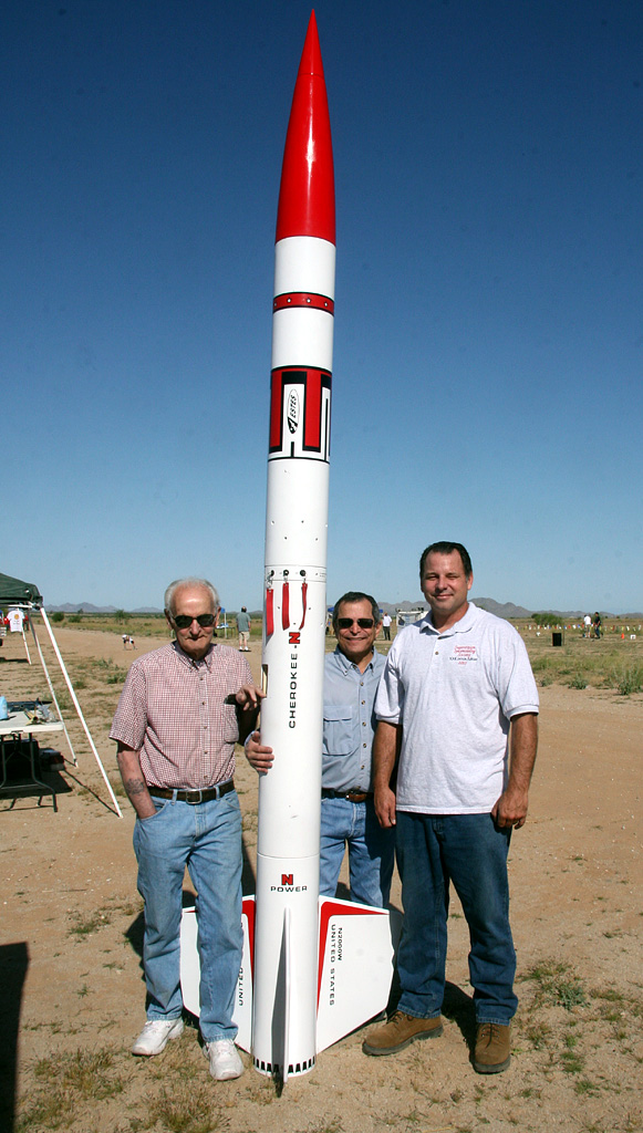
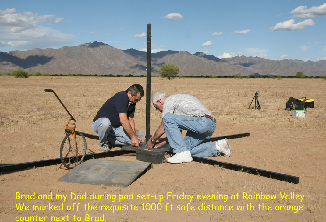
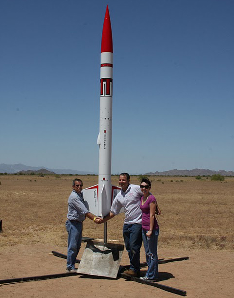
My Dad:
Continuing Love and Support
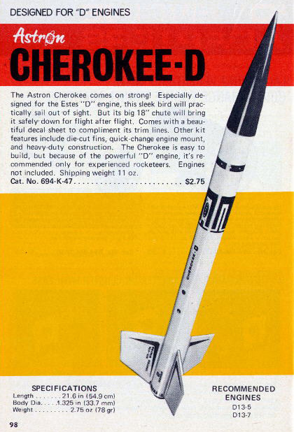
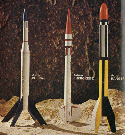
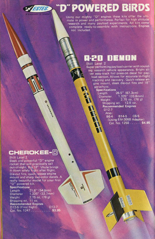
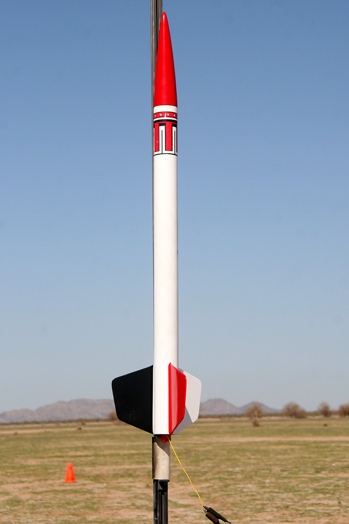
Estes Industries
The original design
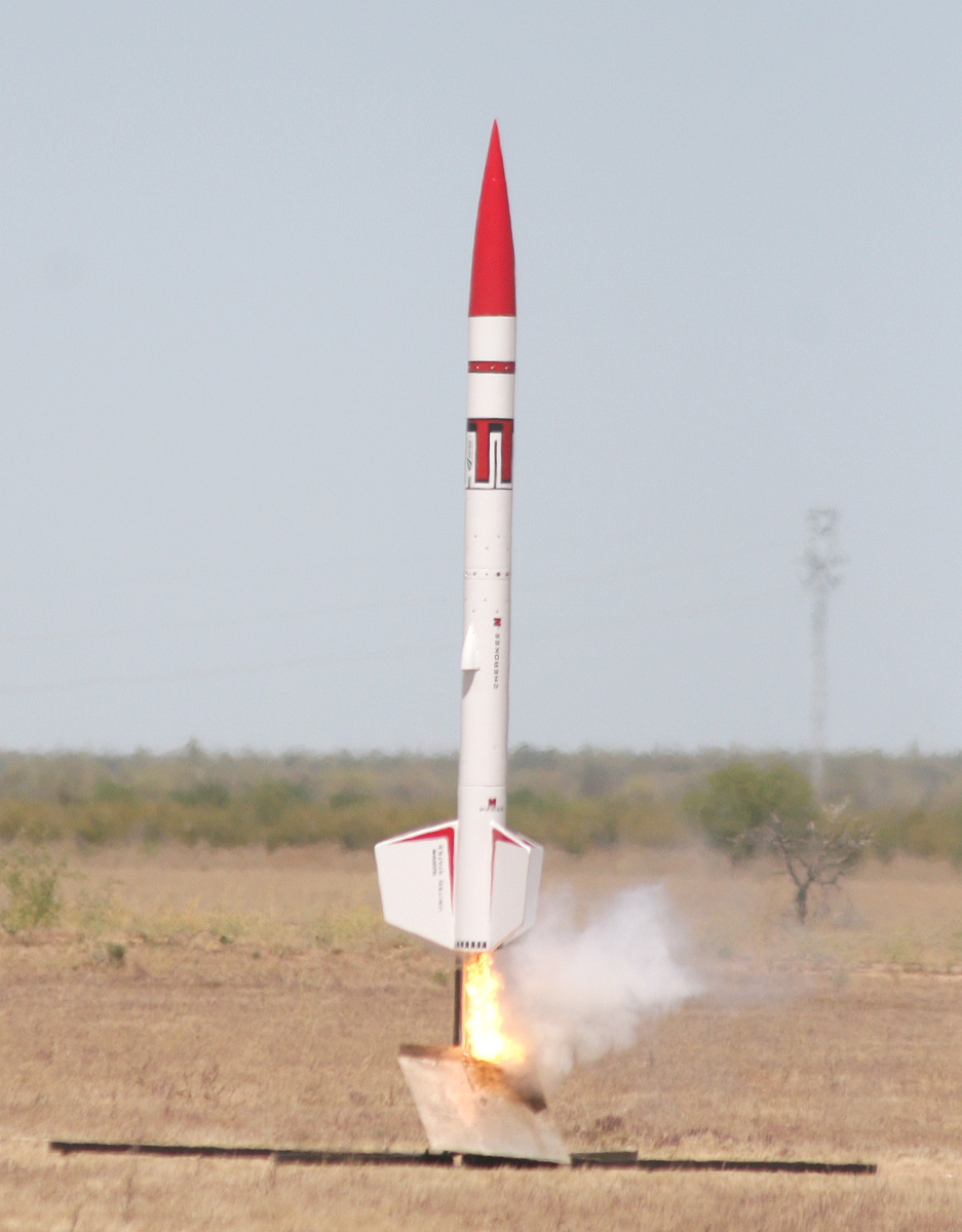
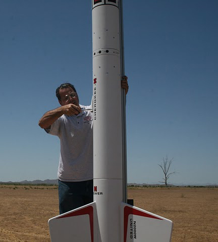
Jim Z's Rocket Plans
Estes CHEROKEE D plans
Apogee Components (RockSim)
Design Software
PerfectFlite Electronics
Primary/backup altimeters
Missile Works
Secondary altimeter
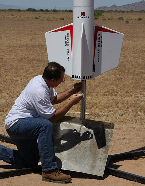
AeroTech Consumer
Aerospace

Motor/hardware
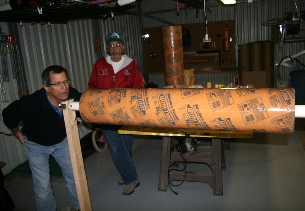
What's Up Hobbies
98mm Fwd Seal Disk
& nylon shock cord
Giant Leap Rocketry
Easyglas Sock and recovery components
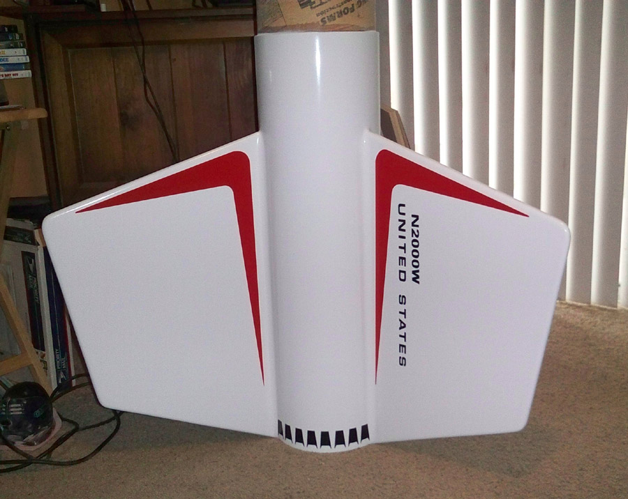
Sticker Shock 23
Custom Vinyl Graphics
Sticky Stuff Sales
Resin/epoxy accessories
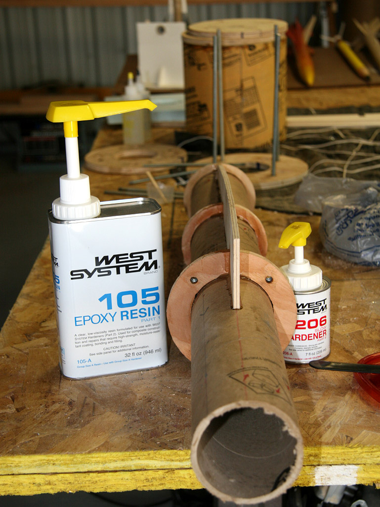
West System
External resin/epoxy
Microfasteners
Nylon shear pins
The Home Depot
Misc. hardware
Lowe's Home Improvement Center
Misc. hardware
Granger IndustrialSupply
Forged eye nuts/bolts
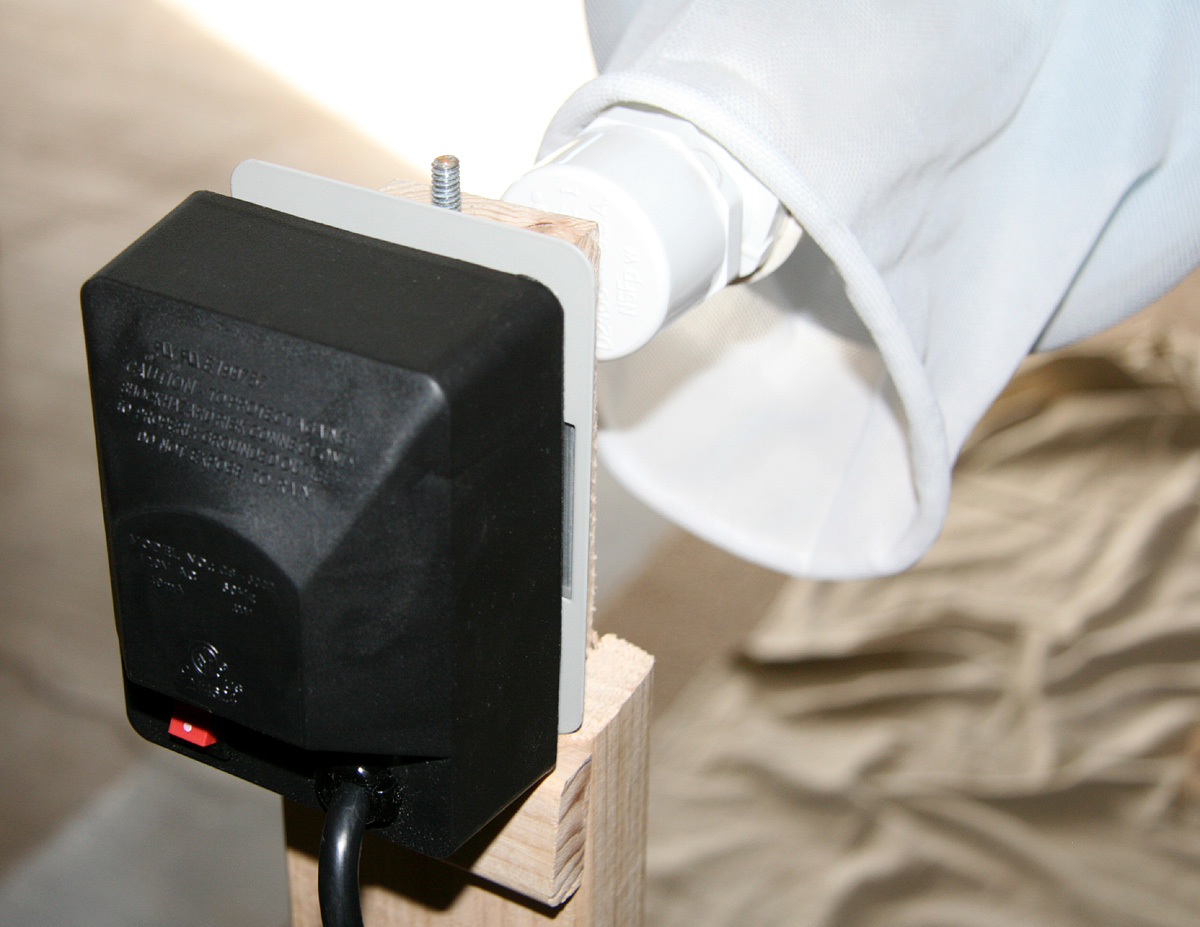
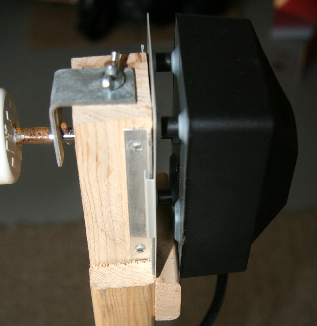
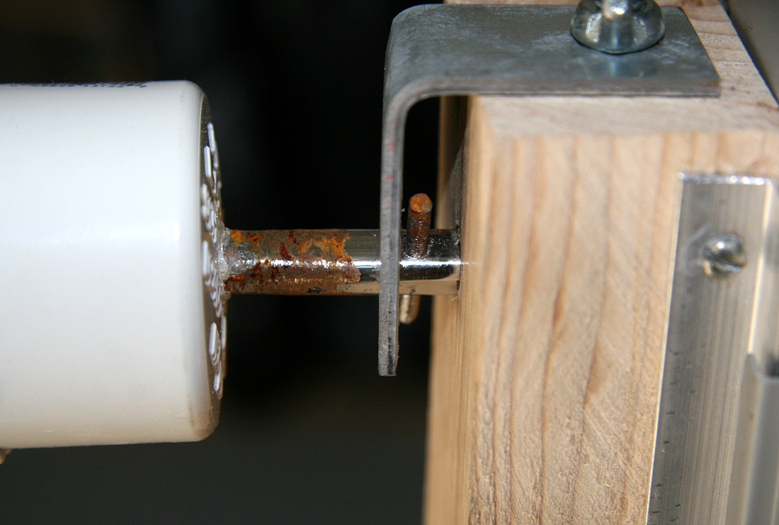
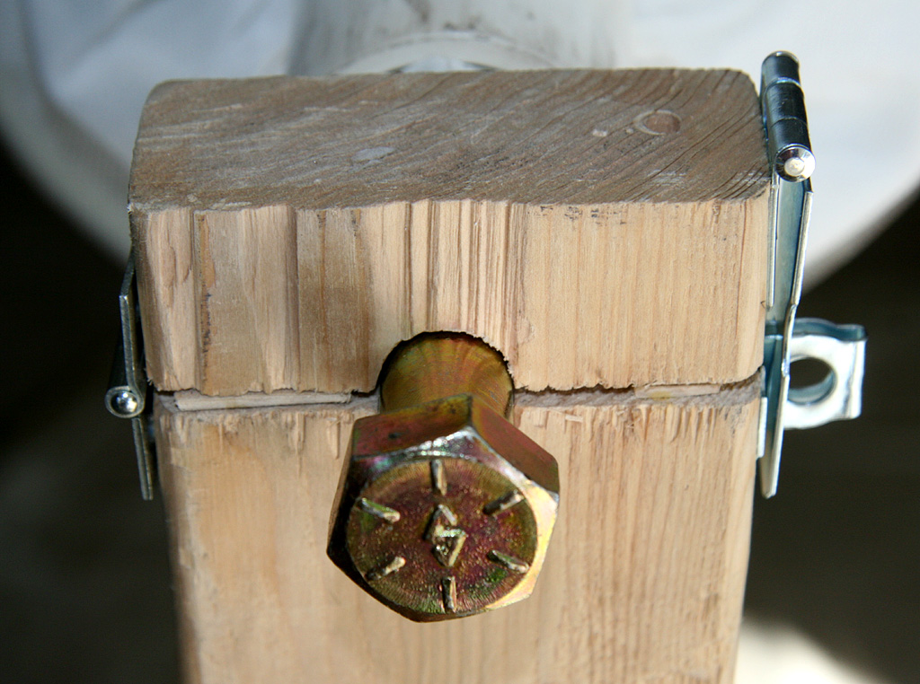
Aerocon Systmes
External Switches
Essence's
Model Rocketry
Reviews & Resources

You name it!
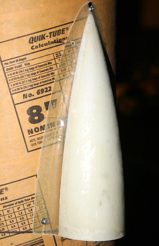
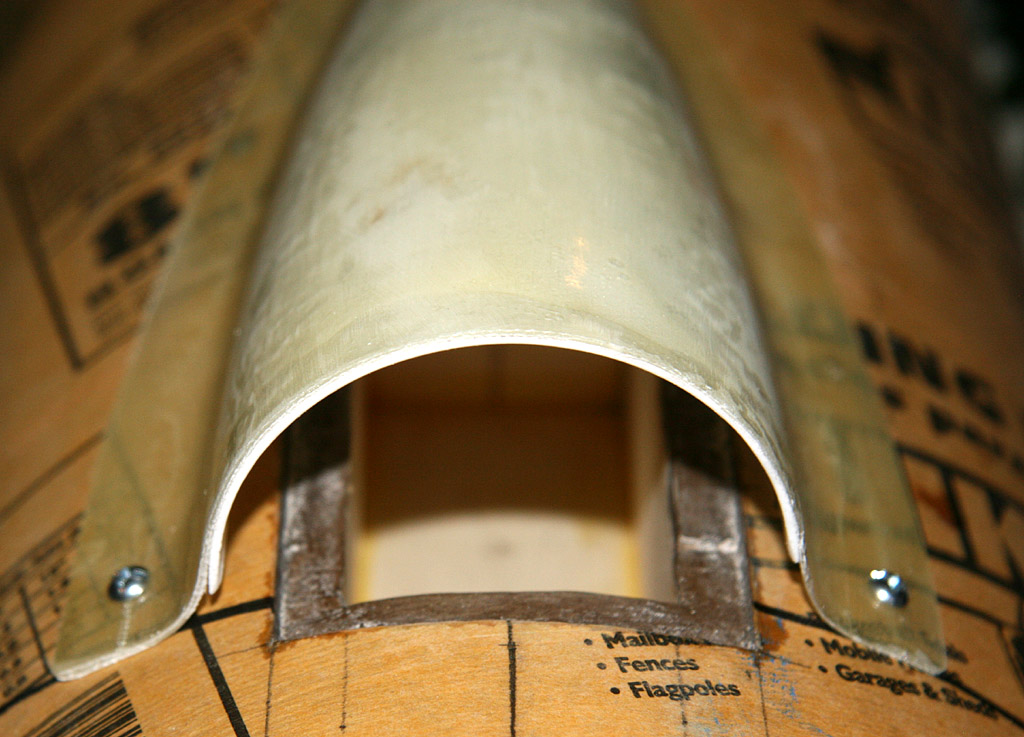
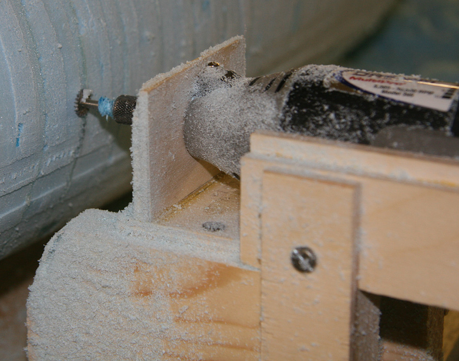
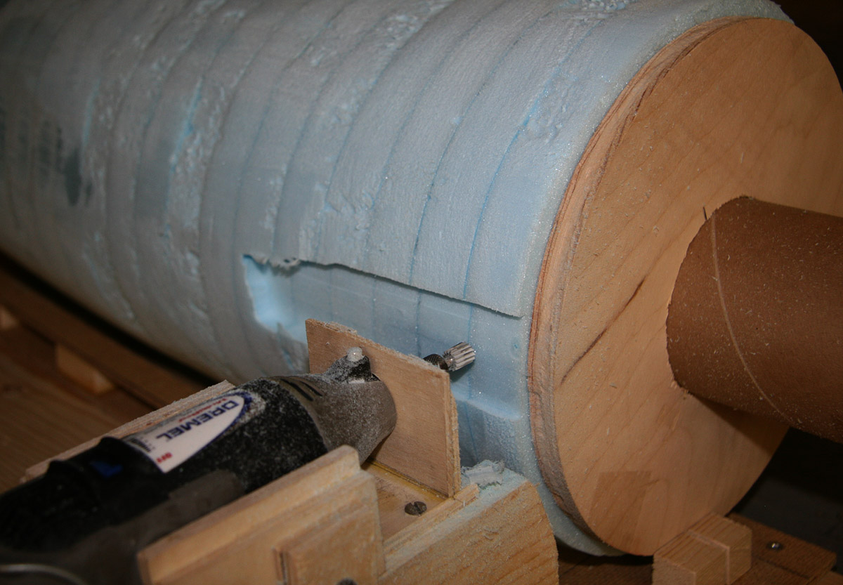
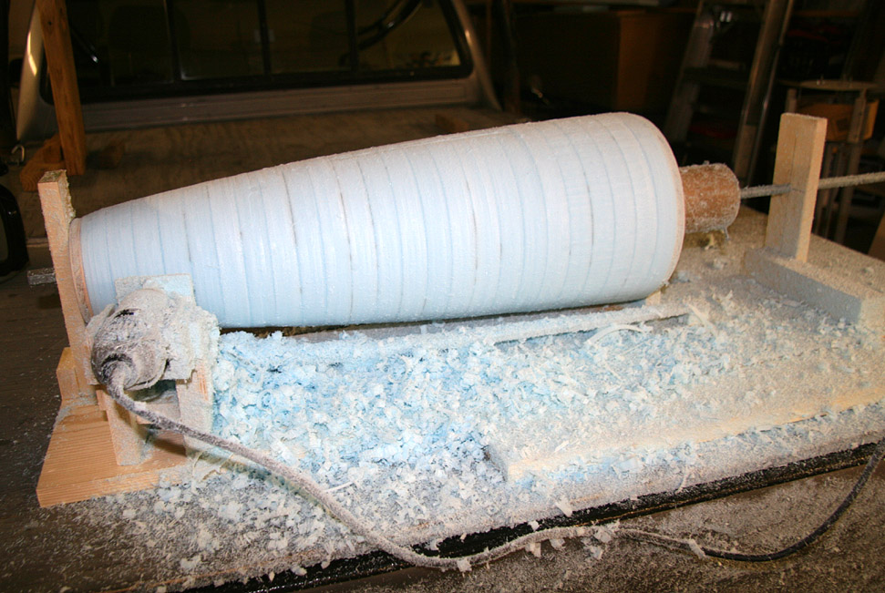
Public Missiles Ltd.
Liquid Two-Part Foam
(1st Nosecone)
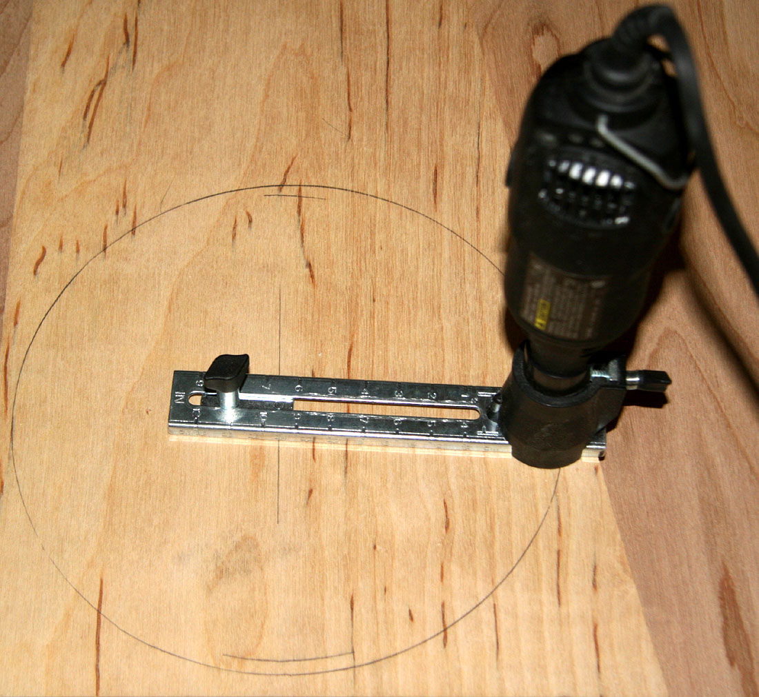
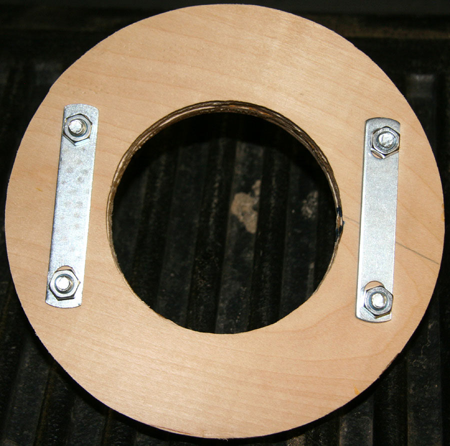
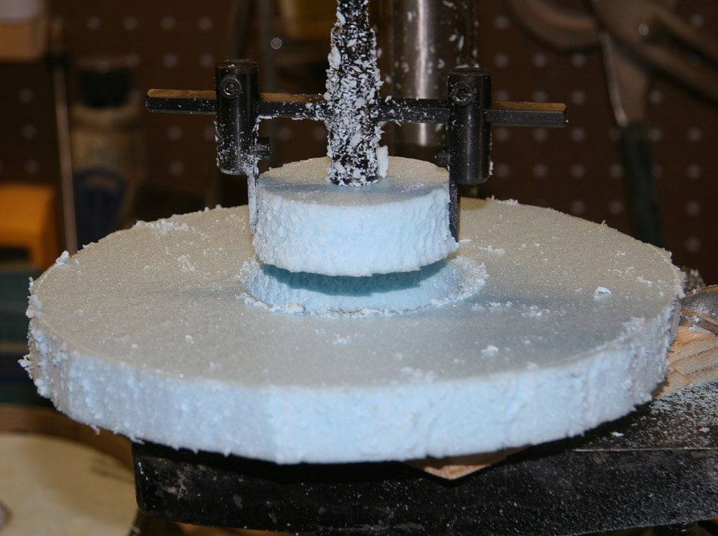
Harbor Freight Tools
Drill Press Circle Cutter
For questions or comments, feel free to email me at: E-Mail Moe!